After only 2 years, my G-450C Yeasu passed QRT.
A strip examination of the electrical motor and the control board indicated that the potentiometer inside the motor and the control board passed out.
I asked to my Hamshop to order spare parts from Yeasu : answord was NUTS ! Rest assusred that it will be my last purchase at Yeasu.
So, I first replace the potentiometer of the electrical motor.
I disconnect the connectors going to control board (excepted for 12v, who was always Ok) and I replace the control board it with a UNO R3.
A basic knowledge of Arduino is requiered.
I decline any responsibility as for the direct consequences or indirect for any nature which could result nature whithch could result by using this solution.
Les explications qui suivent requièrent une connaissance préalable des micro-contrôleurs Arduino, de nombreux tutoriels sont disponibles sur internet. Je décline toute responsabilité découlant de la mise en application de ce qui suit.
Operating Principle :
Toujours la règle du KISS (Keep It Simple Stupid)
Release note 04/17/2023 : Arduino Uno have been replaced by a basic Arduino Nano.
In insert a classical dividing bridge with his output connected on the Arduino's analog input A0. The tension of the bridge is feeded by the +5V reference from the Arduino.
One of the resistors of the dividing bridge is the potientiometer into the rotator motor (VR1 see scheme below)
Depending on the value read on A0 analog input and treated by the Arduino. The treated valuye wil act as a logical On/Off sensor limit switch. (treated value = 0 = limit for CCW rotation / value = 450 = limit for CW rotation)
Scheme 1 : dividing bridge
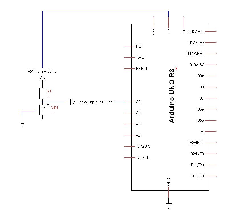
The power supply of the dividing bridge is provided by the +5V reference coming from the Arduino.
RV1 varies with the motor rotation
To determine the value of VR1, whe use the classical formula of a dividing bridge
Dividing factor Θ = VR1/(R1+VR1) (1)
If we speak about the voltages into the bridge we have
- Divided Voltage (= tension at pin A0)
- Input Voltage ( 5V )
We can write : Divided Voltage = Input Voltage x Θ
When replacing Θ by his value (1) : Divided Voltage = Input Voltage x VR1 (2)
R1+VR1
Whe have to determine the value of VR1 , after transforming (2) whe have
VR1 = Divided Voltage X R1
Input Voltage - Divided Voltage
or :
VR1 = R1 X Divided Voltage
Input Voltage - Divided Voltage
This last formulation is VERRY interesting because it is now a VOLTAGE RATIO and it also means that regardless the variations of the voltage coming from the Arduino, the processed result will be a voltage ratio.
Ok that's all ? Not yet...
Before mounting VR1 into the motor, you'lle notice that the measured value of RV1 with your Ohmmeter is not identical that the value measured by the Arduino.
This is due the tolerence of the resistor R1 used into the bridge (most of times the tolerance is going from 5 to 10%).
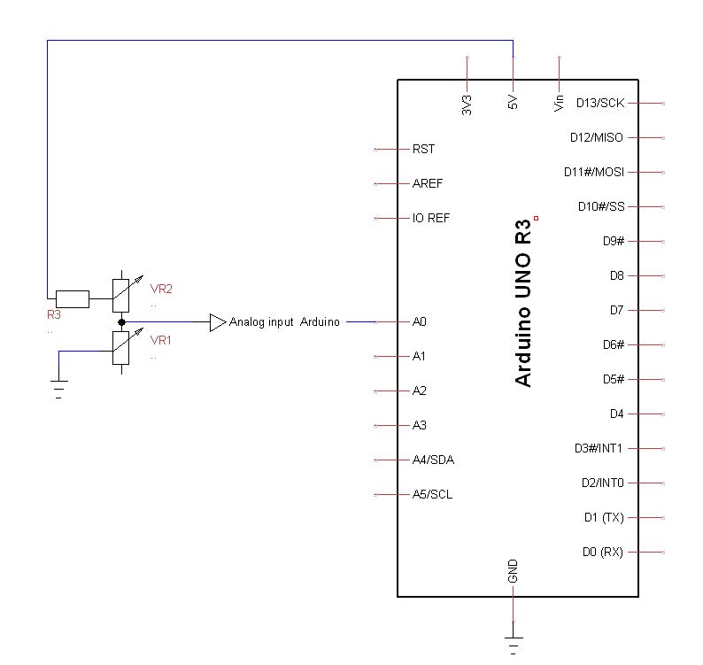
Whe will correct this by replacing the R1 resistor by a resistor R3 + a trim potentiometer VR2 , the sum of the values R3 + VR2 will close of 1.2 to 1.4 times R1 (this will give you a wide tolernace range)
Moreover, R3 provides a shortcut protection of A0 just in the case that VR2 and VR1 are equals to 0.
Scheme Dividing Bridge + Calibration :
Procedure :
- Before mounting VR1 into the motor cage, disconnect VR1 from montage Arduino
- Turn VR1 at his half value
- Measure the value of VR1 whith your ohmmeter between the pins that will be connected to Arduino A0 analog input (write this value)
- Reconnect VR1 to your Arduino be carrefull to not change the position of VR1
- As soon as Arduino displays the value of VR1, adjust VR2 so that the displayed value corresponds to the value you writed previously.
The choice of R1 (ou RV2 + R3) value:
I chose a value for R1 (or R3+RV2) close to max value of VR1.
In this case, VR1 is max 480Ω so I chosed R3=390Ω and VR2 = 100Ω
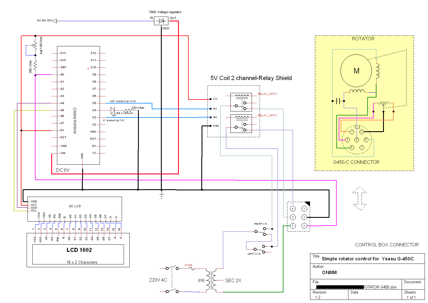
How it works into the G-450C motor
When the rotator is making a rotation from 0° to 450°, VR1 varies between 0 and 450 Ω.
The motor of the G-450C is supplied by a AC voltage about 30V (in stand-by position, measured at the secundary of the supply transformer).
The motor have 2 windings giving the opportunity to turn CW or CCW.
Explaination
VR1 is connected between PINS 2-3 from control box connector.
Push buttons RIGHT CW et LEFT CCW are supplying respively the motor windings CW = pin 4 & CCW = pin 5
VR1 is conneced to A0 from Arduino.
Digital outputs D3, D4, D5 are activated in regard of the processed values from Arduino
If processed value <1 , output D3 is enabled and switch a relay that cuts the supply of the CCW winding, the motor can only turn CW by pressing the push button CW.
Inversly, when the displayed value is > than 450, D5 is activated and the supply of de CW winding is switched off, the motor can only turn CCW by pressing the push button CCW
D4 (Overlap LED) is activated when displayed value is > than 360.
D3 and D5 digital outputs are acting as limit switches.
|
// LCD IIC I2C TWI
// Pin SDA to A4
// Pin SLC to A5
#include <Wire.h>
#include <LiquidCrystal_I2C.h>
LiquidCrystal_I2C lcd(0x27, 2, 1, 0, 4, 5, 6, 7, 3, POSITIVE); // Set the LCD I2C address
int analogInput = 0; // define analog input 0
float R1 =390;
void setup()
{
lcd.begin(16,2); // iInit the LCD for 16 chars 2 lines
lcd.clear();
lcd.backlight(); // Turn on the backligt (try lcd.noBaklight() to turn it off)
lcd.setCursor(0,0 ); //First col, first line
lcd.print("HEADING");
pinMode(3,OUTPUT); // define digital pin 3 as output
pinMode(4,OUTPUT); // define digital pin 4 as output
pinMode(5,OUTPUT); // define digital pin 5 as output
}
void loop()
{
float valeurLue = (float) analogRead (analogInput); // readed value on analog input 0
float resistanceLue = (valeurLue * R1)/(1023 - valeurLue); // apply the formula see explanations about divider bridge
float resistanceAffichee = ( int)((resistanceLue * 10.0 + 0.5)/10.0) ;
lcd.setCursor(8,0); //col 8 line 1
if (int(resistanceAffichee) > 360) {lcd.print("+");lcd.print(int(resistanceAffichee)-360);lcd.print((char)223);lcd.print("OVER");}
else {
lcd.print(int(resistanceAffichee));lcd.print((char)223);}
if (int(resistanceAffichee) >= 360) {digitalWrite(4,HIGH);}
else {digitalWrite(4,LOW);}
if (int(resistanceAffichee) <= 2) {digitalWrite(3,LOW);lcd.setCursor(0,1);lcd.print("PLS ROTATE CW");} //col 1, line 2
else if (int(resistanceAffichee) >= 2) {digitalWrite(3,HIGH);}
if (int(resistanceAffichee) >= 448 ){digitalWrite(5,LOW);lcd.setCursor(0,1);lcd.print("PLS ROTATE CCW");}
else if (int(resistanceAffichee) <= 448) {digitalWrite(5,HIGH);}
delay (800); // wait 1000msec between readings
lcd.setCursor(8,0); //1st line
lcd.print(" ");
lcd.setCursor(0,1); //2d line
lcd.print(" ");
}
|
")
")