I build last week a Bazooka vertical for the 40m (see link here) with good results.
This inspired me to build a second one and implement a two phased vertical array system.
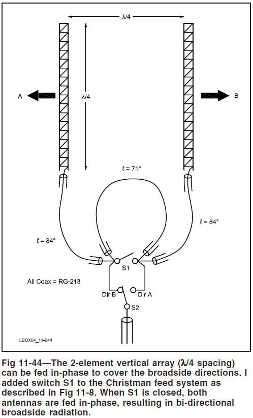
I have chosen for a Christman phasing system : simple and easy o build
Now, praticaly ... simple, yes... but ...
I'll give you here how I made : probably there are better methods. I'm far to be a specialst !
First : start to build two identical vertical bazooka antennas
- Central frequency : 7.050 MHz
- Radials : system of 4 elevated radials 2m above the ground
- Coax used to build the antennas : used H100
- Top extension of the antenna (part C in the illustration below) : 300 Ohm Open Line shortcuted on both ends
- Measured coax velocity factor (*) : 0.82
(*) Don't trust to much the given velocity factor of the coax cables you have : the wise man will verify it with a antenna analyser (I use a MFJ 259-B), sometimes the results are verry surprising -espacialy with old cables laying in the shack since years, or little oxydated or often, the cheap cables coming from 'exotic manufactures'.
I used the formulas given in the page about the vertical bazooka :
The phasing lines ... another storry....
Now, I cut pieces of coax a little bit longer that mentionned, I mounted a connector on one side, and left the other side open and determine with the MFJ-259B the correct quarter wave lenghts. You should find a dip and a value of X=0 or close to 0.
To be sure : I checked at conrresponding frequencies where my lenght of coax react as 3 or 5 quarter waves lenghts, I observed that the X =0 values are more prounonced at higher frequencies.
Example : if your dip is around 6.58 Mhz and indicate a X=1 or 2 , I try at 19.7 Mhz (6.58 X 3) : and I check if X=0 on this frequency, re-adjust if necessary. Repeat those measures several times before cuting in you coax.
Working at higher frequencies allow the work more accuately.
Once the coax pieces ready, I mounted the phasing lines and I used a coaxial relay , I didn't use the K1 relay like illustrated.
Last remarqs :
Your best ennemies :
Making short : how more sophisticated, how more it must be assembled 'in the state of the art'.
Measures :
The measured SWR of phasing in both directions does not exceed 1.3:1 on the entire band.
Practical results :
A strong direction effect and a good F/B is observed.
I made contacts with US stations, using only 50W SSB with succes. Not so bad ....